Radio Controls
Overview
Reference material for the Radio Controls tool/feature in ATAK, sourced from the official ATAK 5.8 Software User Manual (chapter 10, "Radio Controls").
Manual Reference
Select the Radio icon to access controls for the currently supported ATAK radios.

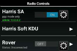
PRC-152-A is a Harris voice and data radio, this enables point-to-point and displays the coordinates of the 152-A SA Radio. Note the text will state whether the device is supported. Harris Soft KDU is a keypad display unit to access the Harris radio controls.
ISRV (Rover) is capable of video downlink from aircraft to ground through a TacRover and TacRover-E.
PRC-152 Connection
Connect to a PRC-152 Harris Radio and select the configure icon on the Radio Controls menu. The Cable Configuration window will display to choose the appropriate cable configuration.

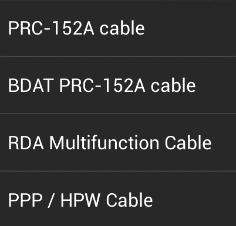
A description of each cable and the radio’s hardware interface is provided. Select OK to exit the cable configuration selection menu.
Slide the OFF button to ON in the PRC-152 section to begin connecting.
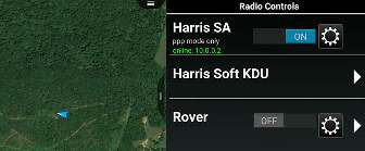
Once a connection is established, point-to-point protocol communication is available and is indicated on the Radio Controls menu. Other radios on the same network will appear on the map once squelched.
Rover Controls
Slide the OFF button to ON in the ISRV (Rover) section to begin connecting through an Ethernet connection. ATAK scans through frequencies to establish an active feed. When the connection is established, the antenna icon will turn from gray to green and will indicate that it is connected.

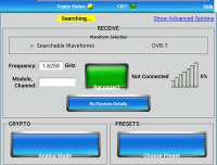
Select the Rover menu item to open the Rover Controls menu. The Status field will indicate the device connection status and the current waveform. The waveform can be changed by accessing the Frequency Scan menu. The Frequency or Module/Channel (DDL) can be changed from the Rover Controls menu, as well as entering the Settings menu, launching the web configuration page for the Rover device, and watch the video. The preset can be added through this interface as well.
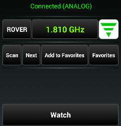
Setting the Module and Channel will automatically change the waveform to DDL. The Recently Used and + buttons have been added to save hand jammed frequencies and DDL, for quicker viewing capability. Tap + to add a channel to the recently used list. Video frequencies and DDL information will not automatically be added to the list.
The frequency can be manually changed by tapping the current frequency entry or by opening the Scan Frequency Range Menu by tapping the Scan button. Change the frequency by entering a Start Freq Code and End Freq Code and selecting OK. ATAK will scan all available frequencies within the established range. Select Next on the Rover Controls menu to advance to the next available stream in the range.

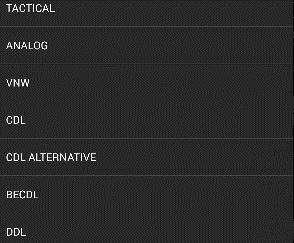
Tap the Waveform drop-down to open the menu of available waveforms and select the desired waveform from the list. Additionally, the user may choose between L-Band, S-Band, C-Band Low and C-Band high, Ku-Band Low, Ku-Band Low (2), and Ku-Band High.
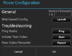
Select the Settings icon to access the Rover Configuration settings. Options are available to initiate the Web based Config for the Rover device in a web browser, Ping Radio, Initiate Test Video, engage the Raw Video Recorder and advanced options.

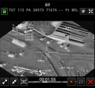
Select the Watch icon to view a video stream.

Source
ATAK 5.8 Software User Manual, 07 July 2026 (Unclassified), pages 45–47.