Placement
Overview
Reference material for the Placement tool/feature in ATAK, sourced from the official ATAK 5.8 Software User Manual (chapter 2, "Placement").
Manual Reference
Locations of interest can be entered using the Point Dropper tool. Select the Point Dropper icon to place internationally standardized markers and other icons on the map, edit the data and share the markers with other network members.

Self Marker
By default, the Self-Marker is displayed as a blue arrowhead with a white outline at the user’s current location. The appearance of the Self-Marker can be customized by navigating to Additional Tools and Plugins > Settings > Display Preferences > My Location Color/Size. Custom options for the Self-Marker include marker size, main color and outline color. To apply custom colors, select the Custom option and use the sliders under Change/Create Icon Main Custom Color and Change/Create Icon Outline Custom Color to create the desired color/outline.

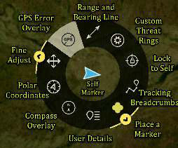
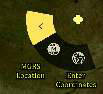
Long-press Fine Adjust to open the sub-radial and enter Coordinate or MGRS Location.

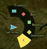
Long-press Place Marker to open the sub-radial to place a CoT marker.
Other TAK users appear on the display as a colored circle. The color of the circle represents the user’s Team affiliation, with additional lettering inside the circle to identify the role of the user on the team. Team Member markers that include a diagonal line indicate that the GPS location is not available. A solid marker indicates that the user has GPS reception.
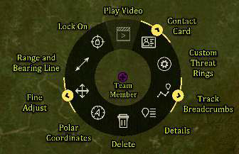
Available roles include: Team Member, Team Lead (designated by a TL in the center of the marker), Headquarters (HQ in center), Sniper (S), Medic (+), Forward Observer (FO), RTO (R) or K9 (K9).
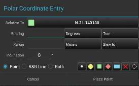
The Polar Coordinate Entry option allows a marker to be placed relative to the current marker. The Polar Coordinate option also allows for a range and bearing line to be placed in addition to the marker (point).
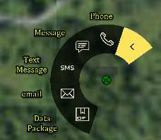
Long-press or tap Contact Card to open the Communications sub-radial. Chat and Send Data Package are always available to communicate with the user. If configured in Settings; Email, SMS Messaging, TAK Chat (XMPP), VOIP and Cell Phone communication options will also appear on the sub-radial.
Point Dropper
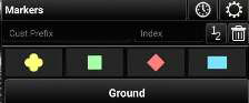
Select the Point Dropper icon to open the Point Dropper menu, which contains several iconsets, recently added points and an Iconset Manager. The basic Markers symbology affiliations are: Unknown, Neutral, Red and Friendly. Select a marker from the pallet, then tap a location on the map to drop the marker.
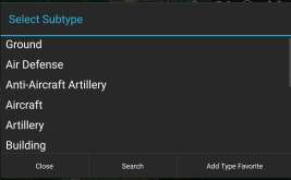
To apply a particular subtype to a marker, tap on the subtype field to reveal the list of available subtypes. Make a selection from the list or use the Search option to search for a particular subtype.
To place a marker using manually entered coordinates, choose the marker type and long-press a location on the map. A window will open allowing for the entry of the desired coordinates (MGRS, Lat./Long, etc.).
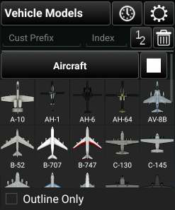
To change the standard naming convention when placing markers, enter values into the custom prefix and index fields. If values are entered, the next marker will be dropped with the prefix name and starting number(s) or letter(s) and every subsequent marker will be assigned the next consecutive number(s) or letter(s).
Select the mission specific iconset to open marker options including Contact Point (CP), Initial Point (IP), BP/HA, Waypoint, Sensor or Observation Point (OP).
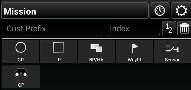
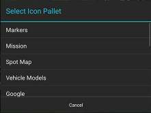
Swipe in the iconset area or select the Iconset Name field, bringing up the iconset drop-down, to move between iconset pallets.
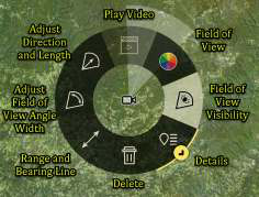
The Mission iconset allows the user to place mission-specific markers. For instance, the Sensor marker can be placed with a visible Field of View (FOV) direction and length. The FOV can be adjusted from the Sensor radial.
The Vehicle Models iconset places to-scale 3D models of the selected icon. If the Edit option is selected, modifications to the model can be made in the same manner as the Rubber Sheet feature.
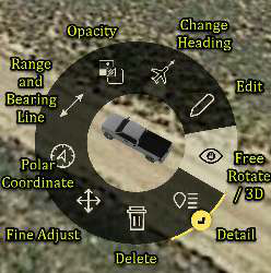
See the Rubber Sheet section for more details. The Free Rotate / 3D View allows the user to quickly access the map rotation and 3D view of the Vehicle Model or other objects on the map.
The Reference Point icon set allows for the placement of reference point markers on the map. A custom prefix, starting index number, background color and font color are all assigned. The Background Color and Font Color can be changed by selecting the color icon.

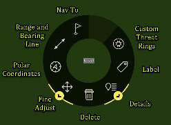
Once a Reference Point is placed the following actions are available from the radial, Fine Adjust, Polar Coordinate, Measure, Nav To, REDs, Label, Details and Delete.
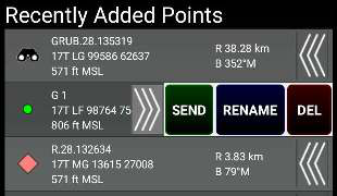
The last point placed is shown at the bottom of the Point Dropper window. The information for all recently placed points can be accessed by selecting the Clock icon. This displays the marker icon, name, coordinates, elevation, and range & bearing information. The user can send, rename or remove any recently added markers by selecting the Arrows next to the marker to reveal SEND, RENAME or DEL buttons.
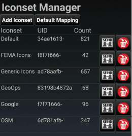
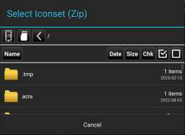
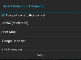
Select the Iconset Manager (gear) button to add or delete iconsets or to set the default CoT Mapping.
Radial Menus
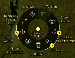

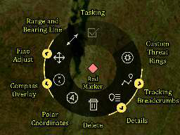
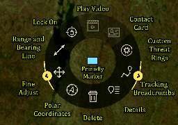
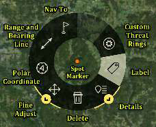
Long-press Fine Adjust to open the sub-radial which allows the ability to enter coordinates or MGRS location. Select Details on a marker radial to make desired modifications, including Affiliation, Name, Coordinates, Elevation, Type, Remarks and Status.
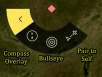

Selecting the marker icon itself, in the top-left corner, allows for the affiliation to be altered. Use the selector to choose a new affiliation, a preview of what the marker will be updated to look like is shown.
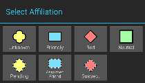
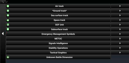
Selecting Type opens a dialog box with additional categories to choose from.
Checking Show Modifiers under Status, provides text fields to record additional information about the marker, including the direction of movement, speed, location, etc. Setting a status also displays a status indicator underneath the marker icon when viewing it from the map. All markers, except for Mission > BP/HA, Spot Map, and Vehicle Models, can place a FOV on the map by setting the sensor switch to Enabled. Selecting Edit will bring up a Sensor pane to change FOV range, direction, field of view, sensor endpoint, and configure a video source.

File attachments, including images and videos, can be associated with the object by selecting the Attachments (paperclip) icon. After choosing an attachment option, a prompt may appear to select the desired application to capture the image/video attachment. Once all the desired modifications have been made, the Marker can be sent to other network members using Send. The information can be broadcast to all members or sent to specific recipients. Select the Auto Send option to broadcast the marker to other TAK users on the network, with updates automatically sent about once every 60 seconds.
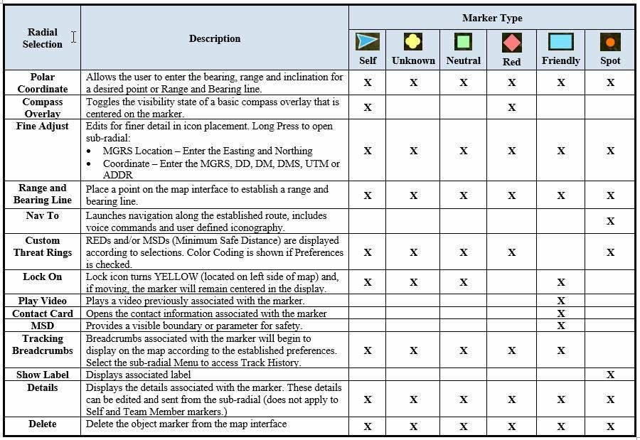
The following table presents the radial menu items and corresponding descriptions. An X indicates if the radial selection appears for each specific marker type.
Source
ATAK 5.8 Software User Manual, 07 July 2026 (Unclassified), pages 12–19.