Range Tools
Overview
Reference material for the Range Tools tool/feature in ATAK, sourced from the official ATAK 5.7 Software User Manual (chapter 3, "Range Tools").
Manual Reference
Range Tools provides several types of measuring tools for measuring direction and distance. Select the Range Tools icon from the Additional Tools & Plugins window to open the Range Tools toolbar. The toolbar includes an R&B circle, dynamic measure line, static measure line and a bullseye.


Range and Bearing Line
The R&B Line tool calculates the distance between two locations on a map, the distance between an object on the map and another point on the map, or the distance between a point on the map and the Self-Marker. Select the R&B Line icon on the toolbar to toggle on (yellow) or off (white). When yellow, tap a point to measure from or long press to measure from the Self-Marker to that point. Once the first point or object is selected, tap another point or object from which to measure. Once endpoints are set, this line is stationary.

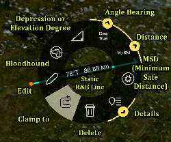
Select the Dynamic R&B Line icon to begin creating a line that can be moved and repositioned by the user. Tap once to place an endpoint, then again for the second endpoint. This R&B Line remains unlocked. Touch and drag an endpoint to move it. When the desired location is established, select the center of the line and use the Pin button on the radial menu to pin the position of the bearing line. This pinned R&B Line will remain after the Dynamic R&B Line is toggled off.

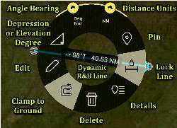
The pinned R&B Line will show the azimuth, distance and depression or elevation degree between the two points. To reposition an anchor point, long press on either end of the bearing line, then tap another location. The line will be moved to the new location with an adjusted distance and azimuth.
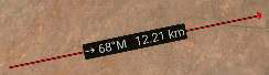
Select either end of the R&B line to display the R&B Line end point radial.

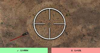
To make fine adjustments to either end of the line, tap the Fine Adjust icon on the radial. Crosshairs appear and the area is magnified. Drag a finger inside the magnified area to finely position the end of the bearing line, then select Confirm to accept the new position or Cancel to discard it. To delete the bearing line, select the Delete icon on the radial and the line will be deleted.
To obtain even further options for the bearing line, tap along the line and the R&B Line radial will display. See Bloodhound (Multiple Bloodhounds) section for more details about the Bloodhound radial option.
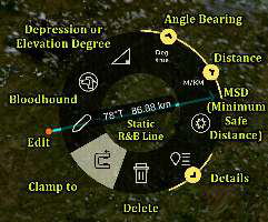
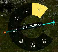
Select the Angle Bearing Units radial to display additional bearing unit options, including Degrees Grid (measured in relation to the fixed grid lines of the map projection), Mils Grid, Degrees Magnetic, Mils Magnetic, Degrees True or Mils True.
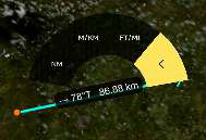
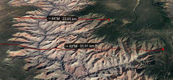
Select the Distance Units radial to display additional distance unit options, including Nautical Miles, Meters/Kilometers or Feet/Miles. If the length of the R&B line is longer than approximately 30km, the line will then follow the contour of the ground versus being a straight line from one endpoint to the other.
To make changes to the parameters of the line, select the Details icon on the radial.
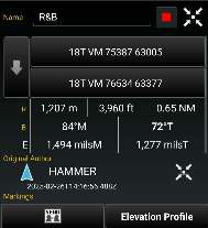
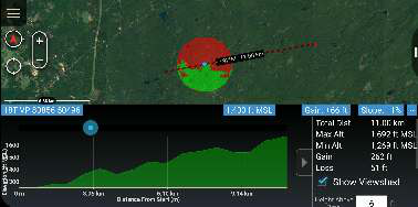
The Elevation Profile option at the bottom of the Details page displays the elevation profile for the selected R&B Line at the bottom of the map when selected. The Elevation Profile provides information on Max Altitude, Min Altitude, Gain and Loss. By checking the Show Viewshed checkbox, a viewshed will be shown along the line. Slide the blue dot left or right to advance the viewshed along the line. The R&B Line can be sent or broadcast to other users from the Details menu.
Range & Bearing Tool settings can be customized in Settings > Display Preferences > Basic Display Settings > Unit Display Format Preferences.
Range and Bearing Circle Tool
The R&B Circle Tool uses one or more range rings to mark a point on the map. Select the Circle icon on the toolbar to toggle the Circle Tool on (yellow) and off (white). When yellow, select the desired location on the map for the center of the circle. If the Self-Marker or a marker is selected for either the center or the radius of the circle, the circle’s center or radius will change when the markers are repositioned.


To make further adjustments to circle parameters, tap the center of the circle to display the circle’s radial menu.
Select the Details icon on the radial to modify the circle center location, the radius, the unit of measurement, the number of rings and remarks. After making adjustments, the circles will be redrawn as specified. The R&B Circle can be sent or broadcast to other users.
Bullseye Tool
The Bullseye tool is an additional Range & Bearing option that gives more information than the standard R&B Line or R&B circle. The Bullseye provides a circular grid with lines every 30 degrees. The angles can be changed to be either toward the center point (Red) or away from the center point (Green).

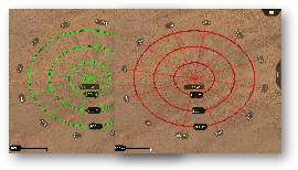
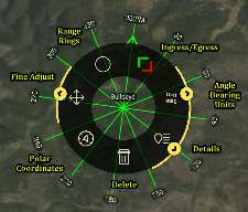
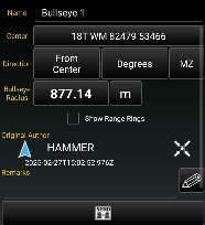
Range rings can also be added. The Bullseye can be sent or broadcast to other users by selecting Send from the Details window.
Source
ATAK 5.7 Software User Manual, 13 March 2026 (Unclassified), pages 19–22.