SLM-10 TAK Integration
Overview
Covers connecting an SLM-10 UAS's ground control station (GCS) and Android EUD into MCHMR/TAK — configuring ATAK's Network Monitor plugin so the EUD can reach the SLM-10's network, then the UAS Tool plugin to forward MAVLink telemetry and broadcast video to MCHMR. A condensed Quick Launch flow for an already-configured kit is at the end.
Prerequisites
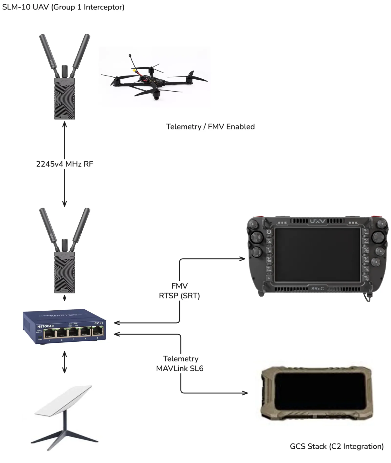
- The SLM-10 kit: a GCS/controller, an Android EUD with ATAK installed, a network switch, a Doodle Labs Mesh Rider Radio, a power bank, three ethernet cables, and a USB-A-to-USB-C (OTG) ethernet dongle adapter.
- Network Monitor, UAS Tool, and Auth Flow are installed on the EUD via Watchtower, and you're already logged into MCHMR.
- The Doodle Labs Mesh Rider Radio's assigned IP address — printed on a label on the radio itself; you'll need it as the gateway for the wired network below.
- An internet-connected backhaul network available for the EUD's WiFi connection (e.g. a Starlink terminal).
This guide is for initial setup. Configure, test, and confirm the system operates without issues before relying on the condensed Quick Launch flow at the end.
Steps
Part 1: Physical Setup
Step 1: Connect the hardware
- Plug the power cords for the radio and the switch into the power bank, then into the radio and switch themselves.
- Connect three ethernet cables from the switch to the GCS, the USB ethernet dongle (for the EUD), and the Doodle Labs Mesh Rider Radio.
- Plug the USB-A-to-USB-C (OTG) adapter into the ethernet dongle, then plug the other end into the Android EUD running ATAK.
- Power on the EUD, then power on the GCS.
Part 2: Network Monitor Configuration
Step 2: Install the plugins
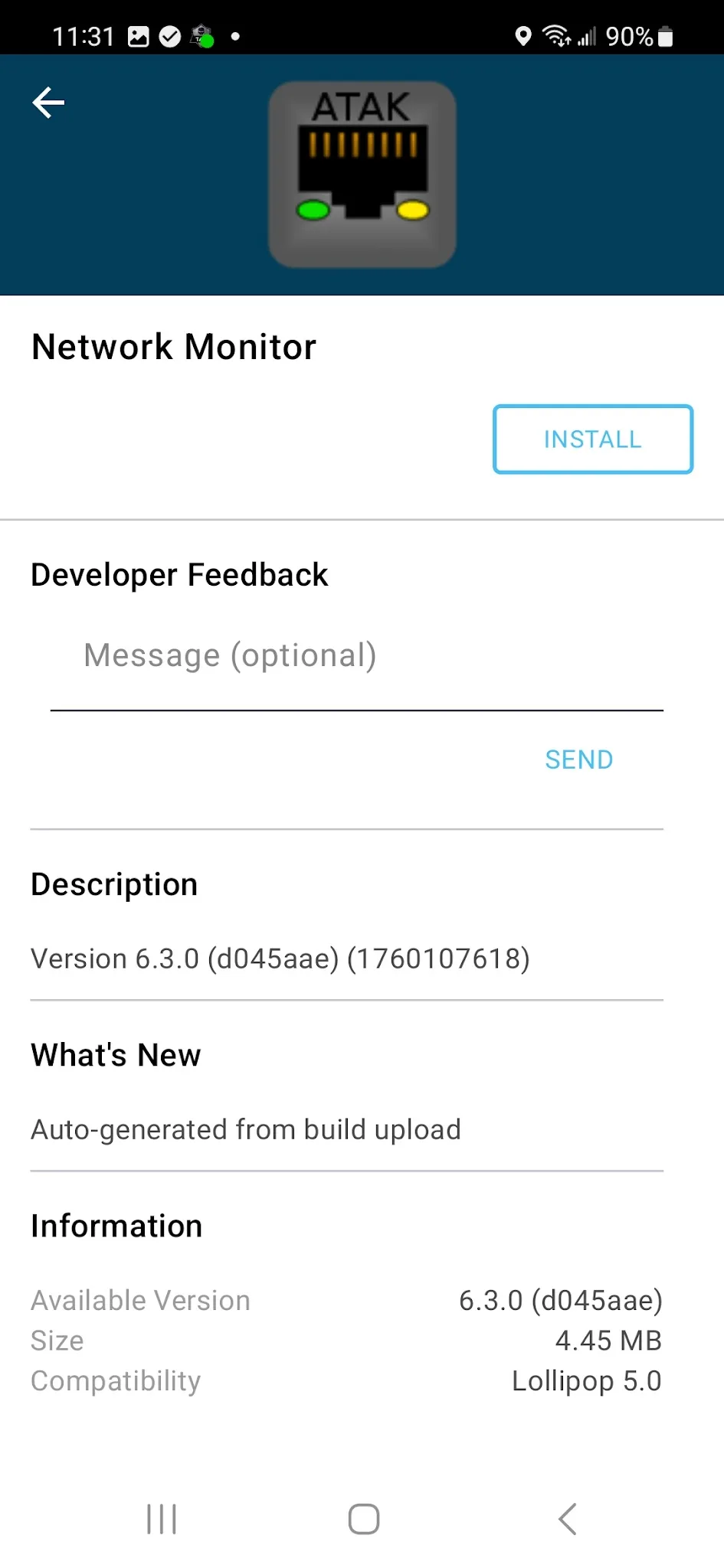
- If Network Monitor isn't already installed, install it (along with UAS Tool and Auth Flow) from Watchtower.
Step 3: Configure the wired connection
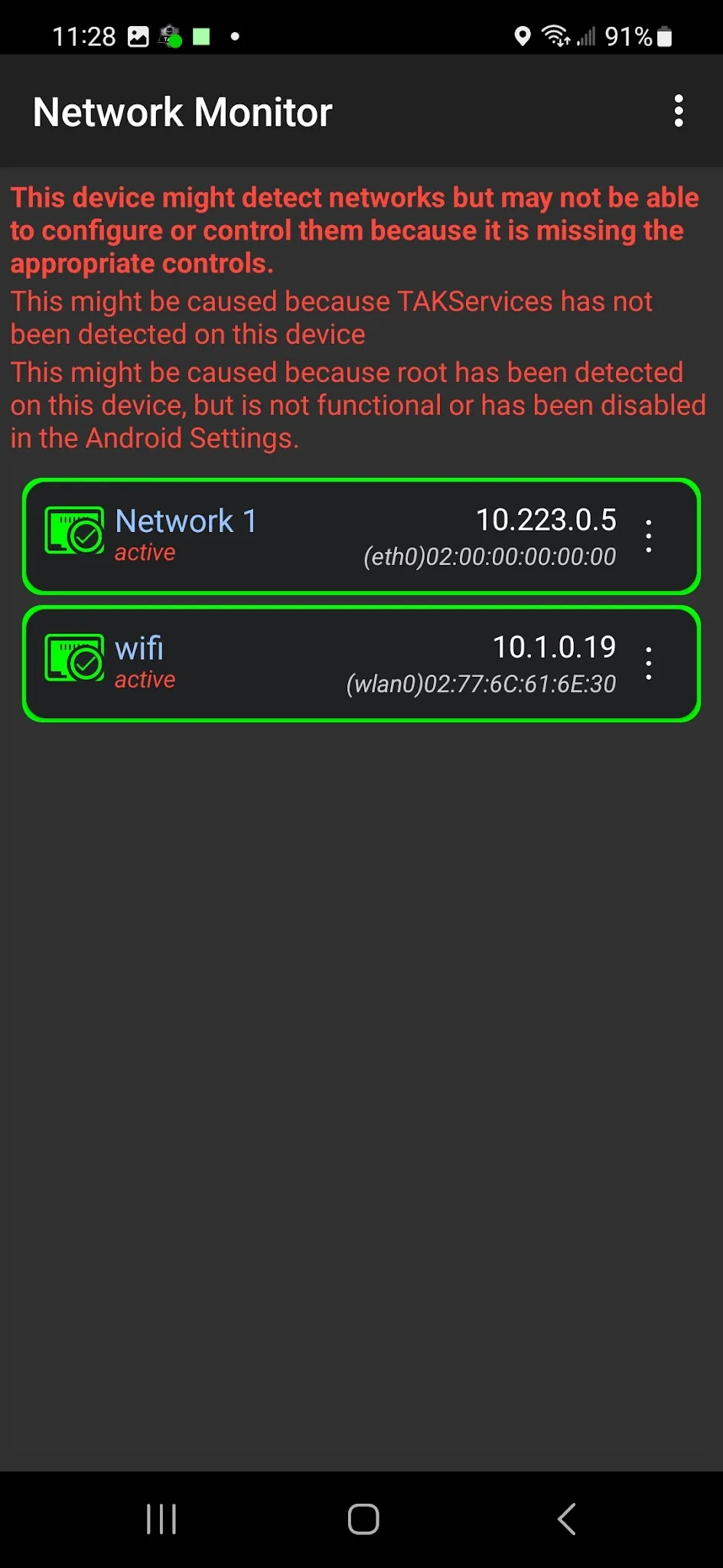
- Open Network Monitor and configure the wired interface (
eth0). Name it — e.g.Network1— and set Network Function to Full Network, Configuration to Static, IP Address to e.g.10.223.0.5, Subnet Mask to255.255.0.0, Gateway to the Doodle Labs radio's own IP (printed on the radio), and check Create Default Route.
Step 4: Configure the WiFi/backhaul connection
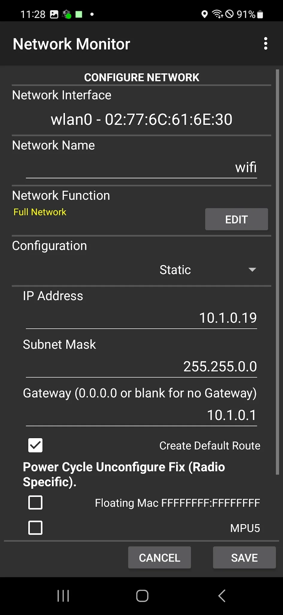
- Configure the WiFi interface (
wlan0) to match whatever internet-connected network you're on — DHCP or static both work. For a static example, set IP Address and Gateway to values in your backhaul network's own range (e.g. a Starlink-style192.168.1.0/24 network), with Subnet Mask255.255.0.0.
Step 5: Verify both connections
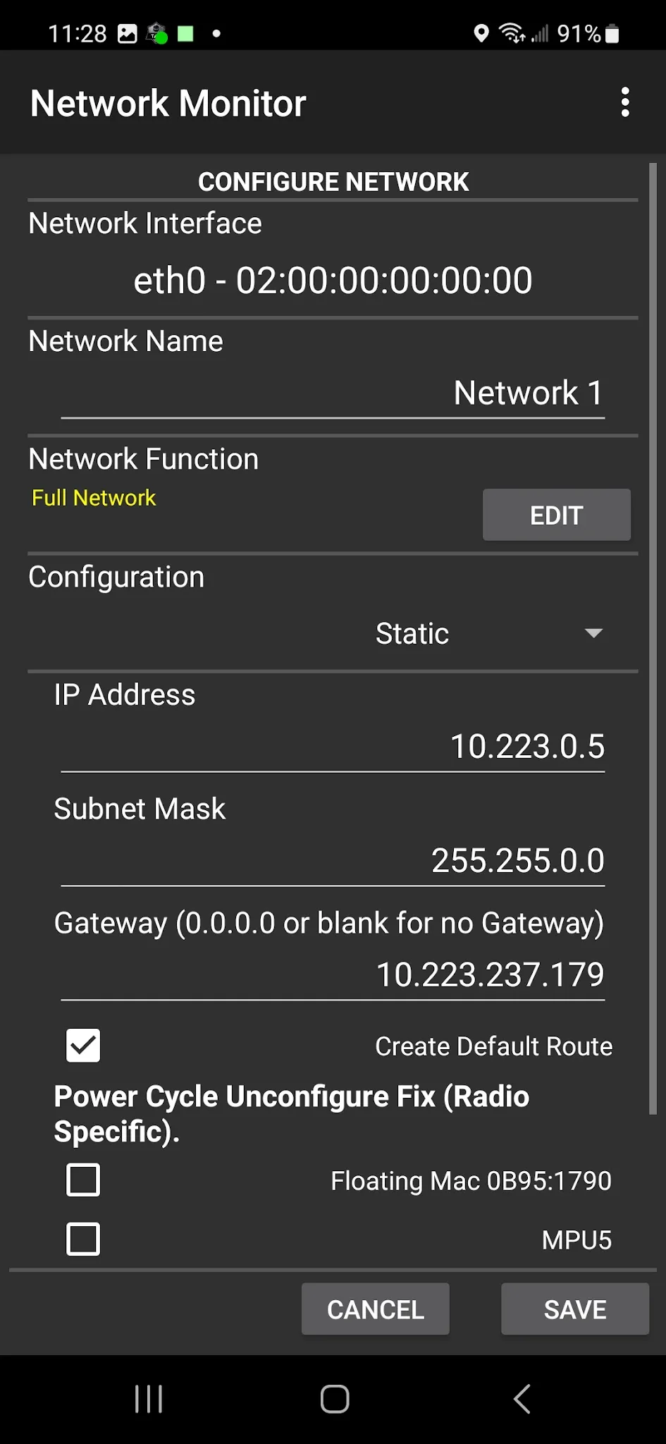
- Confirm both entries show active with a green outline before moving on.
Part 3: GCS (Auterion Mission Control) Configuration
Step 6: Enable Advanced Mode
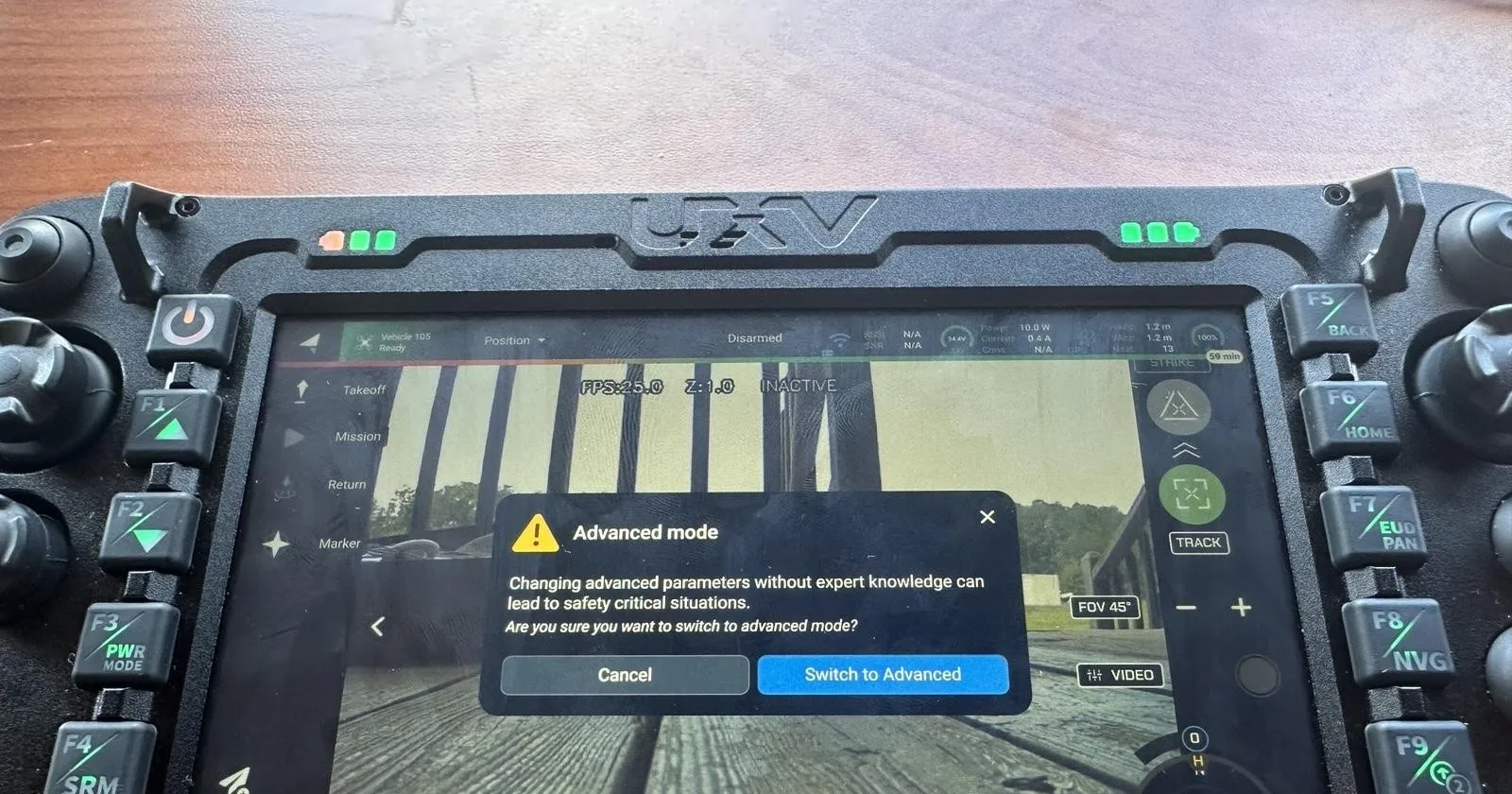
- Open Auterion Mission Control (AMC) on the GCS. Tap the Auterion logo in the upper-left corner six times until the Advanced Mode prompt appears, then select Switch to Advanced.
Step 7: Configure the video proxy
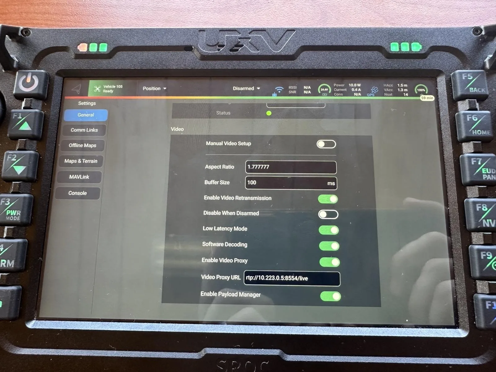
- Open the extended menu and go to Settings → General, then scroll to the Video section. Turn on Enable Video Proxy, and set Video Proxy URL to
rtp://<wired IP of the EUD>:8554/live— e.g.rtp://10.223.0.5:8554/live.
Step 8: Configure MAVLink forwarding
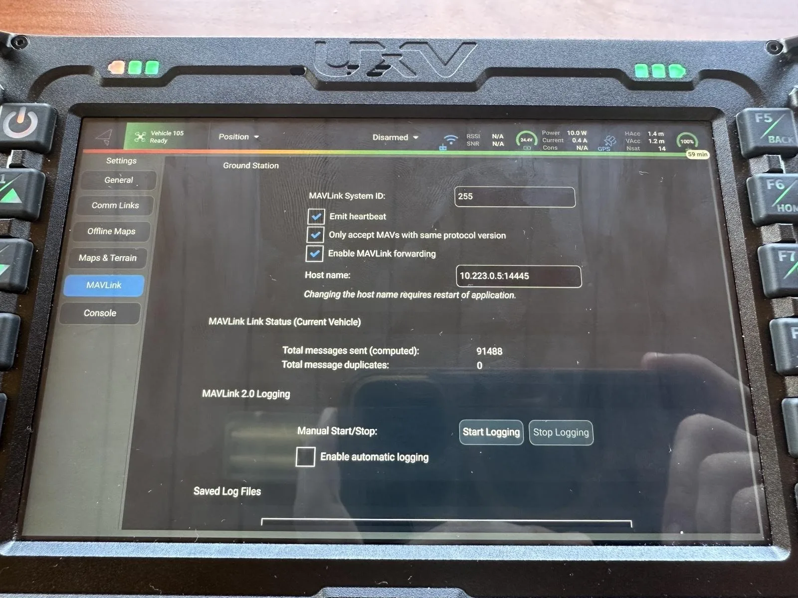
- Without exiting settings, select MAVLink, check Enable MAVLink forwarding, and set Host name to
<wired IP of the EUD>:14445— e.g.10.223.0.5:14445.
Per Auterion's own documentation, a properly-set-up GCS will have a static IP of
10.223.0.4, subnet mask255.255.0.0, gateway10.223.0.1, and DNS8.8.8.8. This is the GCS's factory-standard network configuration and will likely not need to change.
Step 9: Save and restart
- From the menu, select Fly to save the configuration, then close or restart the AMC app.
Part 4: ATAK UAS Tool Configuration
Step 10: Confirm the plugin is loaded
- Open ATAK on the EUD and open the UAS Tool from the extended menu. If it isn't there, open Plugins, rescan with the blue arrows in the upper-right corner, and confirm the UAS Tool checkbox is checked.
Step 11: Configure the MAVLink Platform settings
- From the UAS Tool, tap the settings button and select the MAVLink Platform. Set Default Sensor Type to MAVLink, Video Source Network Adaptor to
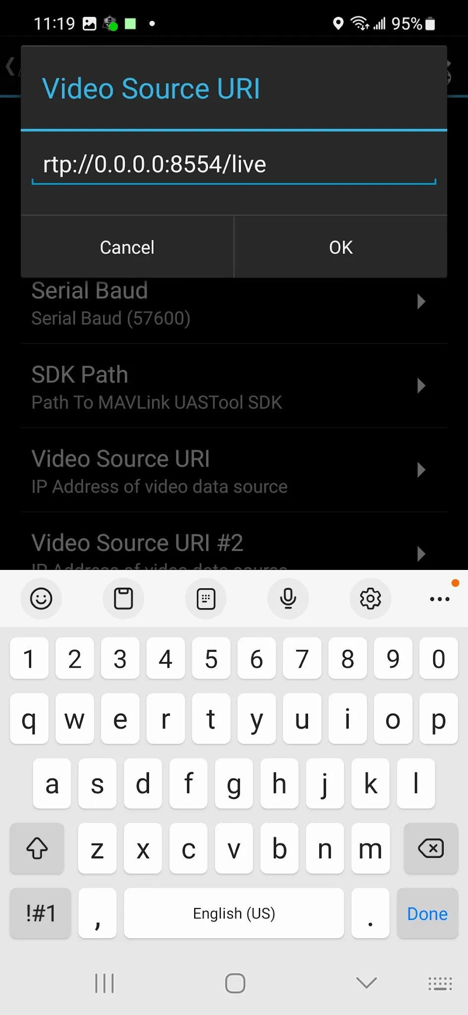
Network1(the name you gave the wired connection in Network Monitor), MAVLink Platform IP to127.0.0.1, Platform Port to14550, Local Port to14445, Serial Baud to115200, Video Source URI tortp://0.0.0.0:8554/live, and Video Source URI #2 tortp://127.0.0.1:8554/live.
Step 12: Configure the video broadcast destination
- Still in UAS Tool settings, select Video Broadcast. Set Video Broadcast Destination to RTSP-Push, Video Destination IP Address to
compass.mchmr.us, Video Destination Port to554, and Video Broadcast Identifier to[drone name]/group/AFCENT— e.g.ambush/group/AFCENT. - Leave Video Destination Username and Password unset, and Reliable P2P Connection off.
The Video Observer URL builds itself automatically from the settings above — you don't need to enter it separately.
Step 13: Add the platform and start it
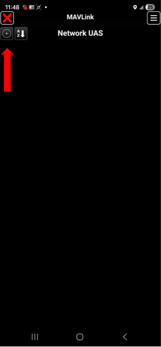
- Back at the UAS Tool's main screen, tap the + icon to add the platform for this session. Set Platform to MAVLink, Network Protocol to UDP, Local Port to
14445, Camera Component to MAVLink, Video Source Adapter toNetwork1, Video Source URI tortp://0.0.0.0:8554/live, and Video Source URI #2 tortp://127.0.0.1:8554/live. Tap OK.
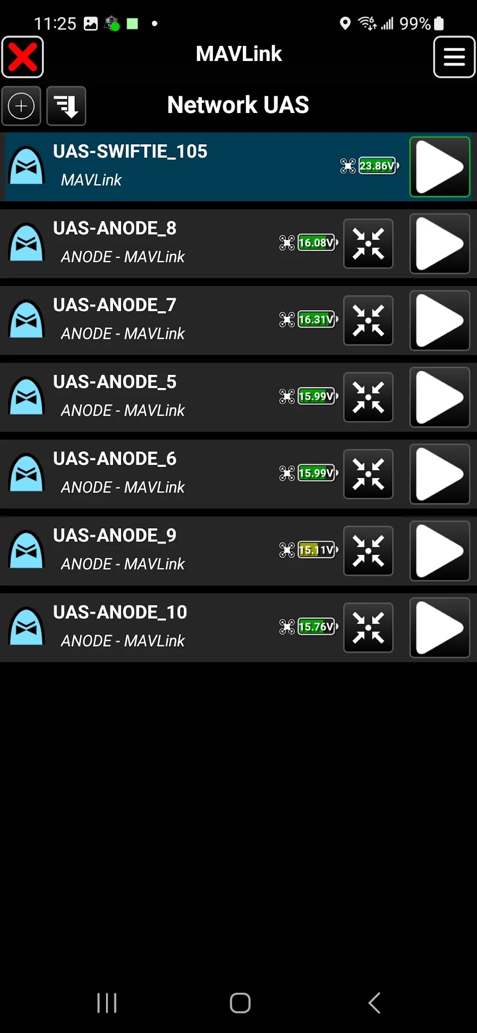
- Find your own connection in the Network UAS list — in testing this showed up as
UAS-SWIFTIE_105— and tap its Play button to connect.
Several
UAS-ANODE_*entries may also appear in this list — these are simulated test aircraft present on the same network, not the SLM-10 itself. Make sure you tap Play on your own device's entry, not one of these.
Step 14: Start the video broadcast
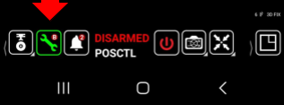
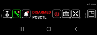
- Tap the wrench icon in the toolbar, then tap the broadcast/play button next to it to start streaming.
Step 15: Restart
- Restart both the AMC and ATAK apps once the initial configuration above is complete.
Quick Launch (Sustainment Use)
Once a kit has been fully configured and tested using the steps above, use this condensed flow for routine launches:
- Plug in power for the radio and switch.
- Plug in the three ethernet cables: switch → GCS, switch → ethernet dongle, switch → Doodle Labs Mesh Rider Radio.
- Plug the USB-A-to-USB-C (OTG) adapter into the ethernet dongle and the EUD.
- Power on the EUD, then the GCS.
- Open Auterion Mission Control (AMC) on the GCS.
- Open ATAK on the EUD, then open the UAS Tool plugin.
- Tap + and verify the quick configuration settings: MAVLink local port
14445, Videortp://0.0.0.0:8554/live. - Tap the Play button on the EUD.
- Tap the wrench icon, then tap the broadcast/play button in the UAS Tool screen.
- Tap Fly on the GCS.
- Fly in accordance with established tactics, techniques, and procedures (TTPs).
This procedure is complete once all of the following are true:
- Both Network Monitor connections show active with a green outline
- The GCS's video proxy and MAVLink forwarding settings save without error
- The SLM-10's connection appears and connects in the UAS Tool's Network UAS list, separate from any simulated
UAS-ANODE_*entries - Video begins broadcasting to
compass.mchmr.us:554under your broadcast identifier
Troubleshooting
- Video Observer URL shows a
?in the link: the Reliable P2P Connection checkbox is checked. Uncheck it — the connection will not resolve correctly while it's on. - GCS won't route traffic to the EUD, or settings don't seem to save: confirm the GCS itself is still on its factory-standard network configuration (static IP
10.223.0.4, subnet mask255.255.0.0, gateway10.223.0.1, DNS8.8.8.8) before changing anything else — this shouldn't normally need to change. - Settings aren't populating correctly in UAS Tool (e.g. Network1 doesn't appear as a Video Source Adapter option): confirm both Network Monitor connections show active with a green outline first — UAS Tool can only see network interfaces that Network Monitor has already brought up. If they're active and it's still not showing up, restart ATAK.
- Nothing seems to take effect after configuration: restart both the AMC and ATAK apps — this is a required step after initial setup (Part 3, Step 15), not just a troubleshooting measure.